This section provides details on optical port cabling specifications for the Assured Delivery Blade (ADB) and associated Host Bus Adapter (HBA).
SFP Modules
The interfaces on the ADB and HBA-0204FC are two 4 Gbps Fibre Channel (FC) SFP optical module ports. The ADB optical ports run a Solace proprietary protocol. The HBA optical ports run standard fibre channel protocols.
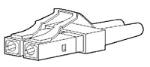
These interfaces provide FC connections using an LC physical connector (shown below) for optical fiber connections using shortwave laser optics. The ADB and HBA SFP modules are field-replaceable and hot-swappable.
Fibre Optic LC Connector
ADB Faceplate LEDs
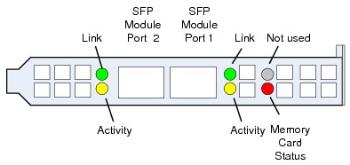
Faceplate LEDs on the ADB indicate the link status for the two ADB SFP module ports, and the read/write status for the Flash Memory Card. One green and yellow status LED is used for each SFP module port, and one red status LED is used for the internal flash memory card, as shown in the figure below.
The Green Port Link Status LED indicates the state of the SFP physical link:
- Off—Either no link to the SFP module has been established, the module is not receiving power, or the cable connection is not secure.
- On—The link to the SFP module has been established, the module is receiving power, and the cable connection is secure.
- The yellow activity status LED indicates whether there is data activity for the SFP modules:
- Off—The SFP module is not receiving or transmitting messages (including network acknowledgments).
- ON—The SFP modSule is receiving and transmitting messages (including network acknowledgments).
The Red Memory Card Status LED indicates the state of the flash memory card:
- Off—No reading or writing of spooled messages from the flash memory card.
- On—Initialization, read, or write operations are occurring for the flash memory card.
The blade carrier containing the ADB must not be removed from the chassis when this LED is On.
Faceplate LEDs on Assured Delivery Blade (ADB-000000-02 Shown)
Connecting to ADB and HBA SFP Devices
The SFP modules on ADBs and associated HBAs use LC connectors for Fibre Channel connections using shortwave laser optics over multi-mode optical fiber (MMF) cable.
- The ADB mate link uses a proprietary cell-based protocol. Refer to the first table below for the associated optical loss budget and operating distance.
It is recommended that the maximum difference in length between the two cables required for the mate link does not exceed 20 m.
- The HBA-0204FC operates according to the 4 Gbps Fibre Channel specification. Refer to the second table below for the associated optical loss budget and operating distance.
The Fibre Types listed in the tables below are synonymous with the following IEC 60793-2-10 specifications:
- A1b fibre type—62.5/125 mm MMF core diameter; TIA-492AAAA-A; ISO/IEC 11801 OM1; INCITS-T11 M6.
- A1a.1 fibre type—50/125 mm MMF core diameter; TIA-492AAAB-A; ISO/IEC 11801 OM2; INCITS-T11 M5.
- A1a.2 fibre type—50/125 mm MMF-850 core diameter; TIA-492AAAC-A; ISO/IEC 11801 OM3; INCITS-T11 M5E.
- A1a.3 fibre type—50/125 mm MMF-850 core diameter; TIA-492AAAD-A; ISO/IEC 11801 OM4; INCITS-T11 M5F
Optical loss budget and operating distance for Fibre Channel physical interfaces over IEC 60793-2-10 MMF are defined in INCITS T11 FC-PI-5 Clause 8.2 and FC-PI-4 Clause 8.2. As per these clauses, the loss budget includes all losses in the fibre media, including splices and connectors, and the minimum operating distance over all fiber types is 1.7 ft. (0.5m).
| Fibre Type | Loss Budget | Operating Distance |
|---|---|---|
|
Type A1b |
1.78 dB |
231 ft. (70 m) |
|
Type A1a.1 |
2.06 dB |
495 ft. (150 m) |
|
Type A1a.2 |
2.88 dB |
656 ft. (200 m) |
|
Type A1a.3 |
2.95 dB |
656 ft. (200 m) |
| Fibre Type | Loss Budget | Operating Distance |
|---|---|---|
|
Type A1b |
1.78 dB |
231 ft. (70 m) |
|
Type A1a.1 |
2.06 dB |
495 ft. (150 m) |
|
Type A1a.2 |
2.88 dB |
1254 ft. (380 m) |
|
Type A1a.3 |
2.95 dB |
1320 ft. (400 m) |
Typical Network Applications
Redundant Configuration
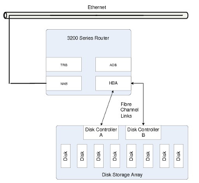
In the deployment example shown in below, the two appliances form a redundant pair configuration and are connected to each other through Ethernet.
The two ADBs are connected to each other through redundant fiber links, and the two appliances are cross-connected to the redundant disk controllers of an external disk storage array through the HBA.
ADB mate links must be directly connected, and cannot go over ethernet or fiber channel switches.
Appliance Network - Redundant Configuration

Non-redundant Configuration
In the deployment example shown in the figure below, the appliance is connected in a point-to-point and non-redundant configuration to the redundant disk controllers of an external disk storage array through the HBA.
All connections are made using standard multimode optical fiber cable equipped with LC-type optical connectors.
This configuration may be used by customers who:
- are expecting to migrate to a redundant appliance configuration in the future, but do not currently need use of the appliance redundancy facility for spooling messages to the external disk storage array
- want to take advantage only of the performance benefits associated with spooling messages to the external disk storage array, without use of the appliance redundancy facility
Appliance Network - Simplex Configuration