Appliance Interfaces
A Solace PubSub+ appliance relies on several interfaces and internal routing components to enable the transfer of data between the appliance and either management applications that connect to the appliance’s management interfaces or client applications that connect to the appliance's Network Acceleration Blade (NAB) interfaces. These components include:
- Management and network physical interfaces, which can be:
- configured and used directly as independent physical interfaces;
- grouped into virtual interfaces, using link aggregation groups (LAGs);
- or used in a combination of independent physical interfaces and LAGs
- IP interfaces: One or more IP interfaces are created for each independent physical interface and for each LAG. Each IP interface must be assigned a unique IP address.
- Message Backbone VRF: This Virtual Routing and Forwarding (VRF) object contains all the NAB interfaces (physical, LAG, and IP), and transports message and topic subscription traffic between client applications and the virtual routers on the appliance.
- Management VRF: This VRF object contains all the management interfaces (physical, LAG, and IP), and transports management traffic between management applications and the event broker.
- IP routes: IP routes are defined independently for the Management and Message Backbone VRFs, associating destination CIDR addresses in the VRF with next-hop gateway addresses. Default routes may also be defined.
The following figure shows the relationship of these components.
Default Solace Interface Configuration After Running the Setup
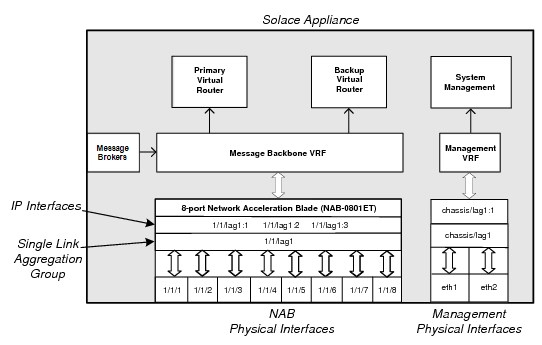
The configuration shown above is that which is created after running the initial appliance set up through the setup privileged EXEC CLI command using default configuration parameters. By default, the physical interfaces on the NAB are grouped into a single LAG named lag1 upon completing the initial software configuration procedure. This provides a single IP address associated with the NAB interfaces through lag1.
As further discussed in this section, the configuration of the Solace interfaces can be modified as required to best suit your deployment requirements.
Physical Interfaces
A Solace PubSub+ appliance uses two types of physical Ethernet interfaces:
- Management interfaces: These interfaces handle traffic from management applications such as SolAdmin, Secure Shell (SSH), and Simple Network Management Protocol (SNMP). There are two management interfaces on the appliance motherboard, and their physical Ethernet ports can be found at the rear panel of a appliance. The management interfaces are identified as
eth0andeth1for a Solace PubSub+ 3230 appliance andeth1andeth2for a Solace PubSub+ 3260, 3530, or 3560 appliance. - NAB interfaces: These interfaces handle message and topic subscription traffic from client applications. The NAB interfaces are physically located on the NAB, which is installed in one of the fabric expansion slots at the rear panel of an appliance. The number of physical Ethernet ports on a NAB depends on the model of NAB installed in the appliance. The network interfaces are identified as
<cartridge>/<slot>/<port>(for example, 1/1/1 through 1/1/8).
Physical interfaces are configured through the Interface CONFIG CLI commands, and their system configuration can be viewed through the show interface User EXEC command.
LAGs
Solace PubSub+ appliances support LAGs, as defined in IEEE standard 802.3ad, so that multiple physical Ethernet interfaces can be grouped together to form a single, virtual, link layer interface.
A maximum of one LAG (identified as chassis/lag1) is supported for the management interfaces, while multiple LAGs are supported for the network interfaces on the NAB. The number of LAGs possible for the network interfaces is limited by the number of Ethernet ports present (due to the fact that LAGs reuse MAC addresses allocated for Ethernet ports). LAGs on the NAB are identified as <cartridge>/<slot>/lag<N>.
To client and management applications connecting to the appliance, a LAG appears as a single IP interface, but inside the LAG, packets are transmitted and received on the bundled physical ports. Link Aggregation Control Protocol (LACP) actively monitors the status of those grouped physical interfaces.
Some of the advantages of using LAGs are:
- Simplified application integration: For appliances and applications connecting to them, the group of aggregated Ethernet interfaces in a LAG appear as a single IP address.
- Increased network bandwidth: The capacity of multiple links is combined into one logical link.
- Increased availability: Traffic on a failed link can be redirected to one of the other links in the LAG (that is, the logical port transparently continues to function over the remaining physical ports). This allows for larger client loads per appliance with a longer meantime between service outages.
- More efficient bandwidth utilization: All traffic to or from the logical port is transparently load shared among all of the available physical ports.
You can create independent LACP LAGs and LAGs that act in an active/backup mode, whereby two interfaces or two LACP LAGs are bonded together so that one member acts as the active member, the other as the backup. For more information on active/backup LAGs, refer to Active/Backup LAGs.
The 802.3ad specification defines two modes of LACP–Active mode and Passive mode. LAGs on the appliance always operate in Active mode. Thus, the third-party Layer 2 switches and appliances that support 802.3ad link aggregation can be configured as either Active or Passive mode when connected to the appliances.
Active/Backup LAGs
A LAG can optionally be configured in an active/backup mode whereby two interfaces are bonded together to provide link redundancy protection: one interface in the pair is active, while the other sits idle waiting to become active should a failure be detected on the active link. Typically, these two links terminate on different Layer 2 devices in the network to add protection should one of those devices fail.
The bonded interfaces can be separate physical interfaces (either management or network interfaces). In addition, if you are using a NAB with more than two Ethernet ports (for example, 4x1GE, 8x1GE, or 6x10GE NAB models), the network interfaces on the NAB can also be grouped into an even number of LACP LAGs, and then those LACP LAG pairs can be given an active/backup bonding. That is, the LACP LAGs can be bonded together in an active/backup LAG.
The MAC address for the LAG in active/backup mode is the MAC address of its first member (that is, the first member added to the LAG).
When using the active/backup mode, there are two LAG members: primary and backup. Only one LAG member can be designated active at a time, and the primary LAG member is always designated active unless the backup LAG has more available bandwidth (that is, unless the backup LAG member has more active ports than the primary LAG member), or if it is a NAB port LAG, the switch-active Interface Admin EXEC command is run.
The switch-active command is not persistent, so when used on an LACP LAG pair, subsequent changes in the operational status of one or more physical interfaces in the LACP LAGs may cause activity to revert to the previously active LAG member. If you want to force the backup LAG to remain active under these circumstances, you must shut down the physical ports in the previously active LAG member.
All traffic is sent out or received on the active LAG member only. All incoming messages on the non-active port are dropped.
- For a NAB port LAG, once the backup LAG member becomes active, that switch from the primary to backup LAG member will not be reverted until one of the following events occurs:
- the primary LAG member has more available bandwidth than the backup LAG member (that is, the primary LAG member has more active ports than the backup LAG member)
- the appliance restarts, and the primary LAG member has equal or more available bandwidth than the backup LAG member (that is, at least as many active ports as the backup LAG member)
- the
switch-activeInterface Admin EXEC command is run
- For a management interface LAG, the switch from the backup LAG member back to the primary automatically occurs as soon as the primary LAG member becomes available again (thus, the
switch-activeInterface Admin EXEC command is not supported by management interface LAGs).
An event log is generated for every switch from primary to backup link or vice versa, regardless of its causes (that is, for example, whether it is a link failure or an execution of the switch-active Interface Admin EXEC command).
Possible Active/Backup LAG Configurations
LAGs can be used in active/backup mode for both management and network interfaces:
- For the management interfaces, a single LAG can be created with the two physical Management network interface ports, where one interface is active and the other is the backup. See Active/Backup LAG Pairing for Management Interfaces.
- For the network interfaces, a LAG can be created with:
- Two physical network interfaces on a NAB, where one interface is active and the other is the backup. See Active/Backup LAGs for NAB Network Interfaces.
- Two LACP LAGs that are then bonded together as an active/backup pair. See LACP LAGs in Active/Backup Pairs.
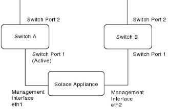
Active/Backup LAG Pairing for Management Interfaces
The figure immediately below shows an example of how the two physical Management network interface ports can be given an active/backup bonding and be connected to separate Layer 2 switches in a data center. This active/backup configuration provides Ethernet port, cable, and Layer 2 switch redundancy for the management access to the appliance.
When a LAG active/backup mode is not being used, it is possible to configure the Management network interface ports as two separate management IP interfaces to the same appliance. This allows for manual redundancy between the Management Ethernet interfaces, which allows an administrator to connect to the IP address of the backup interface if the primary interface is unreachable for any reason.
LAG in Active/Backup Mode on Appliance Management Ports
Active/Backup LAGs for NAB Network Interfaces
The figure immediately below shows an example of two physical network interfaces on a NAB, where one interface is active and the other is the backup. In this example, Port 2 of Switch A and B are both connected to the outside world, while Port 1 of both switches are connected to the NAB. In the event that Switch A fails, physical interface 1/1/2 becomes active and one or more gratuitous Address Resolution Protocol (ARP) announcements are sent out to Switch B.
LAG in Active/Backup Mode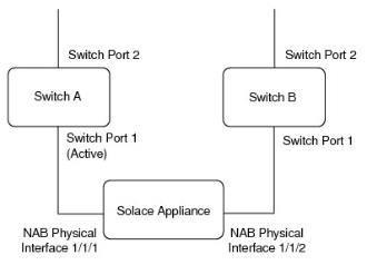
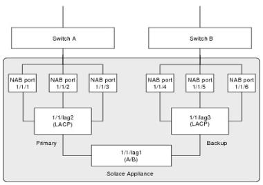
LACP LAGs in Active/Backup Pairs
The figure immediately below shows how two LACP LAGs can bonded together in a single LAG as an active/backup pair. In this example, 1/1/lag1 contains 1/1/lag2 as the primary member and 1/1/lag3 as the backup member.
LACP LAGs in Active/Backup Pairing
IP Interfaces
Each Active/Backup LAG, each LACP LAG that is not part of an Active/Backup LAG, and each physical interface that is not part of a LAG, must have one or more of the following IP interfaces configured for it:
- Static: a static IP interface that can be used to verify that the interface is physically connected and functional (once configured and enabled, a static IP interface is always reachable provided link layer connectivity is intact). This interface type is available in both the Message Backbone VRF and the Management VRF. The static IP interface in the Message Backbone VRF is also used by Solace routing protocols. Client applications can only connect using this address in the Message Backbone VRF if the system is not configured for redundancy.
- Primary: an interface for the primary virtual router. This interface type is only available for interfaces contained in the Message Backbone VRF, it is not supported in the Management VRF.
- Backup: an interface for the secondary virtual router. This interface type is only available for interfaces contained in the Message Backbone VRF, it is not supported in the Management VRF.
An IP interface is identified by the physical interface or LAG it is associated with, and is given an interface index number of 1, 2, or 3. For example, for physical interface 1/1/5, 1/1/5:1 could identify the primary IP interface, while 1/1/5:2 could identify the backup IP interface on that same physical interface. A given index can be assigned any of the interface types, that is, primary, backup, or static.
Interface indices "2" and "3" are only supported for interfaces contained in the Message Backbone VRF, they are not available for interfaces in the Management VRF.
Primary interfaces are activated when the primary virtual router is locally active. Similarly, secondary interfaces are activated when the backup virtual router is locally active. Therefore, from an IP routing standpoint, the primary and backup IP interface states can go in and out of activity depending on the configuration and state of the virtual routers.
- IP interfaces contained within a VRF are configured through the VRF IP CONFIG CLI commands, and their system configuration can be viewed through the
show interfaceUser EXEC command. - Shutting down the physical interface also disables any associated IP interfaces. However, the IP interfaces can be individually configured to be shutdown separate from their associated physical interface.
VRFs
Virtual Routing and Forwarding (VRF) is a network technology that allows multiple instances of a routing table to coexist within the same event broker at the same time. Because the routing instances are independent, the same or overlapping IP addresses can be used in the VRFs without conflicting with each other.
Each IP interface on an appliance is contained within either the Management VRF and Message Backbone VRF objects. These default VRF objects keep management and message traffic and routing tables separate.
The Management VRF and Message Backbone VRFs are preconfigured on an appliance through the setup Privileged EXEC CLI command. The Management VRF is assigned to interface eth1, and the Message Backbone VRF is assigned to <cartridge>/<slot>/lag1.
Management VRF
The Management VRF handles the following types of traffic for a Solace PubSub+ event broker:
- CLI or SSH sessions
- Secure File Transfer Protocol (SFTP)
- Secure Copy (SCP)
- SNMP
- Solace Element Management Protocol (SEMP)
- LDAP
- Syslog
- NTP/PTP
This management traffic is handled through the following physical interfaces:
- For Solace PubSub+ 3260s, 3530s, or 3560s: eth1 and eth2 (and associated static IP interfaces eth1:1 and eth2:1, or LAG interface chassis/lag1:1)
- For Solace PubSub+ 3230s: eth1 and eth0 (and associated static IP interfaces eth1:1 and eth0:1, or LAG interface chassis/lag1:1)
Message Backbone VRF
The Message Backbone VRF handles the client messaging and topic subscription traffic that is exchanged between the network interfaces on the NAB and the virtual routers on the appliance. To support high-availability (HA), redundant Solace PubSub+ event broker pairs, a primary and backup virtual router can be configured on each physical appliance.
The primary and backup virtual routers always exist on an appliance—they cannot be created nor deleted. However, if you are using a non‑redundant Solace PubSub+ event broker, configuring a backup virtual router is optional because the primary virtual router is always active, and the backup virtual router would be idle.
Primary IP interfaces are created in the Message Backbone VRF to support the primary virtual router, and these primary IP interfaces are only activated when the primary virtual router is locally active. Likewise, secondary IP interfaces are used to support the backup virtual router, and these secondary IP interfaces are only activated when the backup virtual router is locally active.
IP Routes
When a client or management application connects to the event broker, the event broker will always send traffic to that application over the same IP interface that initially received the application’s incoming TCP connection (that is, the interface that the application is “connected to” at the TCP layer). If the application’s IP address is part of the same IP subnet as the selected egress interface, the outbound traffic can be sent directly to the application over that interface, and no additional routing is needed.
However, if the application’s IP address is in a different IP subnet than the egress interface’s subnet, than the outbound traffic must be forwarded to a next-hop IP event broker or gateway. IP routes are used to determine the IP address of that next-hop gateway.
When messages need to be forwarded to a next-hop gateway, the Message Backbone and Management VRFs use the following types of routes to choose the correct next-hop gateway:
- Global specific routes
- Per-interface default routes
- Global default routes
You configure the CIDR address used by the applications, and the associated next-hop IP address. This next-hop address must be reachable over the interface that the client is connected to.
Per-interface default routes may be used for any traffic addressed to an IP address for which a global specific route has not been defined within the VRF. You configure the default next-hop IP address, and the interface within the VRF that the default route is associated with. For the Message Backbone VRF, the interface specified must be a physical or LAG interface, for the Management VRF, the interface specified must be an IP interface. Per-interface default routes are recommended in situations where the individual physical or LAG interfaces in the VRF are connected to different subnets.
Global default routes may be used for any traffic addressed to an IP address for which a global specific route has not been configured within the VRF and a per-interface default route has not been configured on the interface that the application is connected to. You configure the default next-hop IP address. This next-hop address must be reachable over the interface that the client is connected to. Global default routes are recommended in situations where the individual physical or LAG interfaces in the VRF are all connected to the same subnet.
The routing information can be configured through the route VRF IP CONFIG command.
As shown in below, the Solace PubSub+ event broker uses these different types of IP routes in the order listed above. That is, during a routing table lookup, the event broker first attempts to use global routes that use a specific CIDR address. If these routes are not found, then it attempts to use the per-interface default route for the interface that the destination is connected to, and if those routes are not found, it attempts to use the global default route.
Routing Table Lookup Flowchart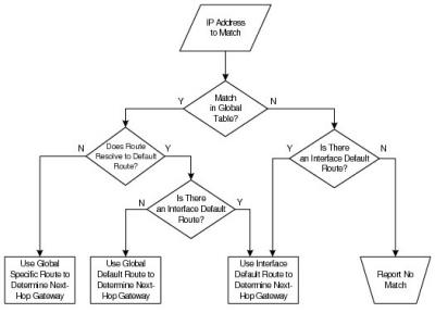
Physical Interface Configurations
This section lists the configuration options supported for both the management interfaces and the network interfaces on the NAB.
- The configuration that is possible for the network interface depends on the model of NAB used by the event broker and the number of Ethernet ports it offers. For each of the following configuration examples, an eight-port NAB is used.
- Speed and Duplex are auto-negotiated on copper ethernet interfaces.
Management Interface Configurations
The two following configuration options are supported for the two Management network interfaces:
- Assign independent IP interfaces to each Management port (that is, no LAG configured)
- Group the Management ports into a single LAG in active/backup mode
Grouping the two ports together provides link redundancy protection. Only one link in the pair is active, while the other port sits idle waiting to become active should a failure be detected on the active link.
Possible Management Interface Configurations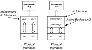
NAB Interface Configurations
The following configuration options are supported for the network interfaces on the NAB:
- Group the NAB ports into one or more LAGs. The number of LAGs possible for the network interfaces is limited by the number of Ethernet ports present (due to the fact that LAGs reuse MAC addresses allocated for Ethernet ports).
- Assign independent IP addresses to each NAB port (that is, no LAG configured).
- A mixture of both, that is, have some of the Ethernet ports grouped into a single LAG, and the remaining ports independently addressed.
Also, as described in Possible Active/Backup LAG Configurations, the network interface ports on the NAB support the concept of a LAG in active/backup mode that allows you to group two ports or two LACP LAGs together to provide link redundancy protection. Only one port/LAG in the pair is active, while the other port/LAG sits idle, waiting to become active should a failure be detected on the active port/LAG.
The following figures show the types of configuration that can be applied to the Solace physical interfaces.
All Network Interfaces Grouped Into a Single LAG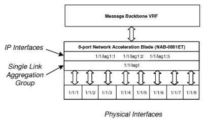
All Network Interfaces Assigned Independent IP Addresses (No LAGs)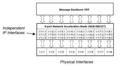
Network Interfaces with Independent IP Addresses and Grouped Into a LAG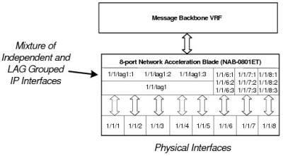
Network Interfaces Grouped Into Active/Backup LAGs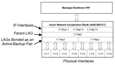
Egress Traffic Shaping
Some Solace NABs implement egress traffic shaping that can be used to delay the output data at rates for its physical interfaces. Although using a NAB’s maximum egress data rate is suitable for a well-designed IP network, such an egress data rate may not be appropriate for an IP network that many contain a mix of high-speed and low-speed interfaces, switches and event brokers with limited buffering, lossy links, and/or background traffic levels that are reach the capacity of the network. If these conditions exist, large numbers of packets may be discarded in the network when the NAB outputs data at the full line rate, resulting very poor goodput from the event broker.
The NAB egress traffic shaping is available on the following NABs:
- NAB-0610EM (all variants)
- NAB-0210EM-04 and later
- NAB-0401ET-04 and later
- NAB-0801ET-04 and later
- NAB-0810EM-01
When egress traffic shaping is offered for a NAB, you can individually configure maximum sustained egress bit rates (in Mbps) for each of its given physical interfaces.