This section describes how to remove and replace blades in deployed Solace PubSub+ 3260s. Separate procedures are provided for the two styles of FECs that used by a PubSub+ 3260 chassis.
- Refer to NAB Replacement before undertaking replacement of a NAB.
- Refer to ADB Replacement before undertaking replacement of an ADB.
- Refer to HBA Replacement before undertaking replacement of an HBA.
ESD/Safety Precautions
Before replacing a system blade, review the following safety warning.
To prevent equipment damage from Electrostatic Discharge (ESD), always ensure that the appliance chassis is electrically connected to earth ground. Always follow ESD prevention procedures when removing and replacing power supplies. Use an anti-static wrist strap, or another anti-static device. If no wrist strap or mat is available, ground yourself by touching the metal part of the chassis.
Tool and Equipment Requirements
The following equipment and tools are required to remove and replace system blades housed in a PubSub+ 3260 FEC:
- electrostatic discharge wrist strap
- anti-static mat
- replacement system blade (ordered from Solace)
- No. 1 Phillips head screwdriver (only for FEC CHS-FC1040-01-C or CHS-FC0140-01-B)
Replacing Blades in CHS-FC1040-01-A or -B or CHS-FC0140-01-A FECs
This section describes how to replace system blades in deployed PubSub+ 3260s that use a FEC with the following marketing numbers: CHS-FC1040-01-A, CHS-FC1040-01-B, or CHS-FC0140-01-A. (The marketing number is indicated on a label affixed to the back of the FEC, which is visible on the rear panel of the appliance.)
This section contains the following topics:
- Step 1: Remove the FEC from the Appliance Chassis
- Step 2: Remove System Blades from the FEC
- Step 3: Install Replacement Blades into the FEC and FEC Back into the Appliance Chassis
Step 1: Remove the FEC from the Appliance Chassis
Perform these steps to remove the populated FEC CHS-FC1040-01-A, CHS-FC1040-01-B, or CHS-FC0140-01-A from the PubSub+ 3260 chassis:
- Enter the power-down Privileged EXEC command to turn off power to the appliance:
solace# power-down
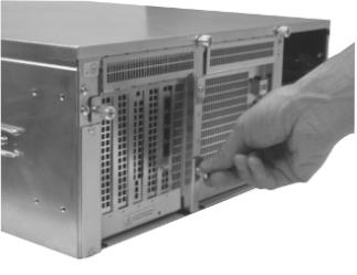
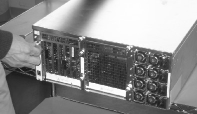
- Loosen by hand the two captive thumbscrews in the upper left and lower right corner of the FEC located within the Fabric Housing 1 or 2 opening at the rear of the appliance chassis (as shown below).
Loosening the FEC from the Chassis

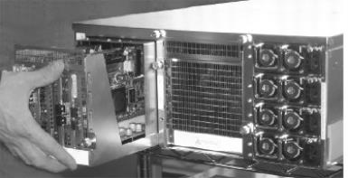
- Gently pull outward on the FEC until its male power connector disengages with the female chassis connector at the rear and slide the FEC straight out from the Fabric Housing 1 or 2 opening.
- Place the FEC on a flat, stable, static-free surface.
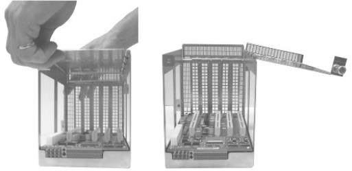
- Looking from the rear of the FEC, loosen the thumbscrew in the upper left hand corner, then pull back slightly on the top lid and flip it over to the right (as shown below).
Opening the FEC
Step 2: Remove System Blades from the FEC
Perform these steps to remove the system blades to be replaced from the FEC:
- To determine the correct location of the blade to be replaced, refer to the tables below for the valid blade slot assignments supported for the FEC used.
Valid Slot Assignments for FEC CHS-FC0140-01-A in Fabric Housing 1 Blade Type Valid Blade Slots NAB-0210EM
1/1 NAB-0401ET 1/1 NAB-0801ET 1/1 and 1/2 TRB-000000-02 1/3 ADB-000000-02 1/4 ADB 04210M-01-A 1/4 HBA 1/5 - Pull up firmly on the blade to be replaced, until it is fully removed from the backplane connector.
Avoid touching the solder side of the blade, pin connectors, or any exposed components.
If an ADB-000000-01 is being replaced, perform these additional steps:
- Remove the plastic cover on the cable channel located at the rear of the FEC backplane.
- Unplug the ADB power cables from the receptacles found on the rear left-hand side of the FEC (as shown below).
Unplugging ADB Power Cables from the FEC Receptacles
- Place the removed blade in anti-static packaging.
Step 3: Install Replacement Blades into the FEC and FEC Back into the Appliance Chassis
Upon completing the removal of the blade to be replaced from the FEC:
- Install the replacement blade into the FEC, and in turn the populated FEC back into the appliance.
- Press the (
 ) on/standby button on the front panel of the appliance, located on the right-hand side below the LEDs, to turn power back on to the appliance.
 - Monitor the LEDs on the front of the appliance to verify that it is powering up properly.
- Verify that the Green LED located in the upper right-hand corner of each power supply is on.
-
The CLI log in prompt displays on your management console screen:
System Software. SolOS Version x.x.x.x
Copyright 2004-2024 Solace Corporation. All rights reserved.
solace>
Replacing Blades in FEC CHS-FC1040-01-C or CHS-FC0140-01-B
This section describes how to replace system blades in deployed PubSub+ 3260s that use a FEC with the following marketing numbers: FEC CHS-FC1040-01-C or CHS-FC0140-01-B. (The marketing number is indicated on a label affixed to the back of the FEC, which is visible on the rear panel of the appliance.)
This section contains the following topics:
- Step 1: Remove the FEC from the Appliance Chassis
- Step 2: Remove System Blades from the FEC
- Step 3: Install Replacement Blades into the FEC
- Step 4: Install the FEC Back into the Appliance Chassis
Step 1: Remove the FEC from the Appliance Chassis
Perform these steps to remove the populated FEC CHS-FC1040-01-C or CHS-FC0140-01-B from the PubSub+ 3260 chassis:
- Enter the power-down Privileged EXEC command to turn off power to the appliance:
solace# power-down
- Loosen by hand the two captive thumbscrews in the upper left and lower right corner of the FEC located within the Fabric Housing 1 or 2 opening at the rear of the appliance chassis (as shown below).
Loosening the FEC from the Chassis
To prevent damage to the system blades, do not twist FEC CHS-FC1040-01-C or CHS-FC0140-01-B when pulling it out of the Fabric Housing opening. Always pull the FEC straight out of the opening, without twisting, until it completely clears the chassis.
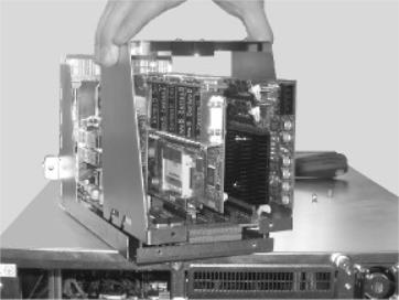
- Gently pull outward on the FEC until its male power connector disengages with the female chassis connector at the rear and slide the FEC straight out from the Fabric Housing 1 or 2 opening.
- Place the FEC on a flat, stable, static-free surface.
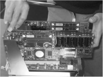
- Looking from the rear of the FEC, use a No. 1 Philips screwdriver to loosen and remove the two screws from the bottom of the metal brace (as shown below).
Removing Screws from Bottom of Metal Brace
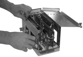
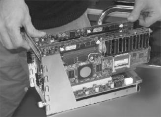
- Carefully remove the metal brace from the FEC by gently pulling it forward slightly from the top while lifting it up so that it clears the chassis and blades (as shown below).
Removing Metal Brace from FEC CHS-FC0140-01-C or CHS-FC0140-01-B
Step 2: Remove System Blades from the FEC
Perform these steps to remove the system blades to be replaced from FEC CHS-FC1040-01-C or CHS-FC0140-01-B:
- To determine the correct location of the blade to be replaced, refer to the valid blade slot assignments listed in the tables below that are supported for the possible FEC types used.
Valid Blade Slot Assignments for FEC CHS-FC1040-01-C in Fabric Housing 1 Blade Type Valid Blade Slots NAB-0210EM
1/1 NAB-0401ET 1/1 NAB-0801ET 1/1 and 1/2 TRB-000000-02 1/3 ADB-000000-011 1/5 Host Bus Adapter (HBA) 1/4 2 Carefully route the ADB power cable through the cable management clip located at the rear of the FEC backplane, then plug the power cable into any one of the four auxiliary power connectors found on the rear left-hand side of the FEC backplane. Valid Blade Slot Assignments for FEC CHS-FC0140-01-B in Fabric Housing 1 Blade Type Valid Blade Slots NAB-0210EM
1/1 NAB-0401ET 1/1 NAB-0801ET 1/1 and 1/2 TRB 1/3 ADB-000000-02 1/4 ADB 04210M-01-A 1/4 Host Bus Adapter (HBA) 1/5 - Using a No. 1 Philips screwdriver, loosen and remove the screw holding down the blade to be replaced in the FEC.
Removing Hold-Down Screw from Blade in the FEC
Do not use excessive force to remove the blade from the FEC. Excessive force may damage the FEC, blade, or both.
- Pull up firmly on the blade to be replaced, until it is fully removed from the backplane connector.
Avoid touching the solder side of the blade, pin connectors, or any exposed components.
Removing Blade from the FEC
If an ADB-000000-01 is being replaced, perform these additional steps:
- Remove the plastic cover on the cable channel located at the rear of the FEC backplane.
- Unplug the ADB power cables from the receptacles found on the rear left-hand side of the FEC.
- Place the removed blade in anti-static packaging.
Step 3: Install Replacement Blades into the FEC
Upon completing the removal of the blade to be replaced from FEC CHS-FC1040-01-C or CHS-FC0140-01-B, install the replacement blade as follows:
- Carefully align the connector edge of the blade with the desired FEC backplane connector.
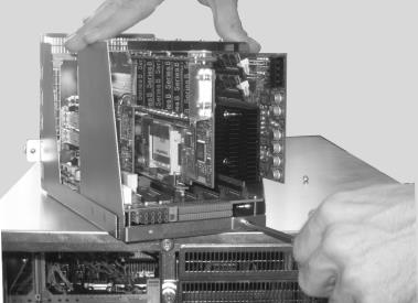
- Push down firmly on the system blade until it is fully seated in the backplane connector (as shown below).
Seating Blade in the FEC
- Facing the front of the FEC, install the two provided SFP modules into the SFP module ports on the ADB faceplate. Refer to SFP Insertion & Removal.
- (NAB-0210EM Only) Facing the front of the FEC, install the two provided SFP+ modules into the SFP+ module ports on the NAB faceplate. Refer to SFP Insertion & Removal.
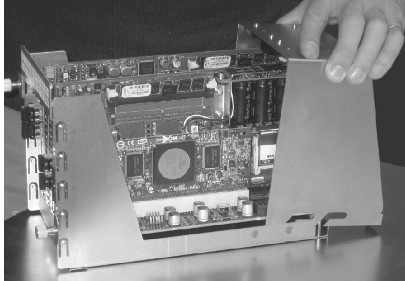
- When you have installed the replacement system blades, carefully slide the metal brace back into place in the FEC so that the grooves on the bottom of the brace engage with the FEC base until the brace is flush with the rear of the FEC (as shown below).
Installing Metal Brace into FEC CHS-FC1040-01-C or CHS-FC0140-01-B
- Using a No. 1 Philips screwdriver, secure the bottom of the metal brace to the FEC using the two screws removed in Step 1.
Step 4: Install the FEC Back into the Appliance Chassis
Perform the following steps to install the populated FEC CHS-FC1040-01-C or CHS-FC0140-01-B into the chassis:
- Position and align the FEC within the Fabric Housing 1 opening found at the rear of the chassis
Placing FEC in the Fabric Housing
- Gently slide the FEC inward and press firmly until its male power connector engages with the female chassis connector at the rear of the Fabric Housing 1 opening.
-
Hand tighten the two captive thumbscrews in the upper left and lower right corner of the FEC to seat it firmly against the chassis.
Securing the FEC in the Chassis
- Press the () on/standby button on the front panel of the appliance, located on the right-hand side below the LEDs, to turn power back on to the appliance.
- Monitor the LEDs on the front of the appliance to verify that it is powering up properly.
- Verify that the Green LED located in the upper right-hand corner of each power supply is on.
The CLI login prompt displays on your management console screen:
System Software. SolOS Version x.x.x.x
Copyright 2004-2024 Solace Corporation. All rights reserved.
solace>