Multi-Site Connectivity Configuration
The following sections provide an example of how you can use Dynamic Message Routing (DMR) to connect applications running at three different sites as follows:
- a cloud provider environment, for example Amazon Web Services
- another cloud provider environment that's different from the first, for example Google Cloud Platform
- an on-premises data center
Before you can enable DMR multi-site connectivity, you must ensure that the requirements discussed in the Prerequisites section are met.
Using This Example
In this example for this configuration, each site consists of an individual cluster that contains a single node, that is a single event broker or a single High Availability (HA) redundant group. External links configured between each node (and therefore, each site). The external links support dynamic subscription learning, and both Direct and Guaranteed message delivery modes.
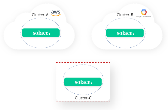
The example below shows clusters created with placeholder names of Cluster-A, Cluster-B, and Cluster-C. The nodes have placeholder names that correspond with the cluster using the notation Broker-<letter_of_cluster>, which represents the router name for that broker. For example, the node is referred to as Broker-A for the cluster named Cluster-A.
Keep in mind that in the sample commands below, the IP addresses, Message VPN names, passwords, and the names Cluster-A, Cluster-B, Cluster-C, Broker-A, Broker-B, and Broker-C are placeholders that you should replace with your own values.
Step 1: Create a Secured Cluster for Each Site
Before you can connect nodes at different sites, you must create a cluster at each site to contain each corresponding node. Each cluster is secured with a a common shared password (we use myshared_secret123 as a placeholder).
To create a secured cluster for each site:
-
Log in to the
Broker-A, enter Solace CLI on the node, and create a cluster namedCluster-A:Broker-A > enable Broker-A# config Broker-A(configure)# routing Broker-A(configure/routing)# dynamic-message-routing Broker-A(...igure/routing/dynamic-message-routing)# create cluster
Cluster-ABroker-A(...uting/dynamic-message-routing/cluster)# authentication Broker-A(...essage-routing/cluster/authentication)# basic Broker-A(...-routing/cluster/authentication/basic)# passwordmyshared_secret123Broker-A(...-routing/cluster/authentication/basic)# no shutdown Broker-A(...-routing/cluster/authentication/basic)# exit Broker-A(...essage-routing/cluster/authentication)# exit Broker-A(...uting/dynamic-message-routing/cluster)# no shutdown -
Log in to
Broker-B, enter the Solace CLI on the node, and create a cluster namedCluster-B.Broker-B > enable Broker-B# config Broker-B(configure)# routing Broker-B(configure/routing)# dynamic-message-routing Broker-B(...igure/routing/dynamic-message-routing)# create cluster
Cluster-BBroker-B(...uting/dynamic-message-routing/cluster)# authentication Broker-B(...essage-routing/cluster/authentication)# basic Broker-B(...-routing/cluster/authentication/basic)# passwordmyshared_secret123Broker-B(...-routing/cluster/authentication/basic)# no shutdown Broker-B(...-routing/cluster/authentication/basic)# exit Broker-B(...essage-routing/cluster/authentication)# exit Broker-B(...uting/dynamic-message-routing/cluster)# no shutdown -
Log in to the
Broker-Center the Solace CLI on the node, and create a cluster namedCluster-C.Broker-C> enable Broker-C# config Broker-C(configure)# routing Broker-C(configure/routing)# dynamic-message-routing Broker-C(...igure/routing/dynamic-message-routing)# create cluster
Cluster-CBroker-C(...uting/dynamic-message-routing/cluster)# authentication Broker-C(...essage-routing/cluster/authentication)# basic Broker-C(...-routing/cluster/authentication/basic)# passwordmyshared_secret123Broker-C(...-routing/cluster/authentication/basic)# no shutdown Broker-C(...-routing/cluster/authentication/basic)# exit Broker-C(...essage-routing/cluster/authentication)# exit Broker-C(...uting/dynamic-message-routing/cluster)# no shutdown
Step 2: Create Cluster Links for Each Site
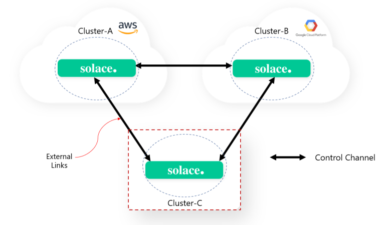
After you create a cluster for each site, you can create a bi-directional link between nodes to establish control channels. Once a control channel is established, the subscription sets needed by nodes at each site can be exchanged with the other. In addition, the subscription sets are dynamically kept up-to-date as local client and queue subscriptions change. In this section, we log in to the node in each cluster and create cluster links (external links) between each site. This configuration creates a control channel across the three sites.
This multi-site connectivity configuration example shows a full mesh (that is, each cluster is connected by external links to all other clusters). This allows subscription propagation and data flows to occur between all clusters. For more information about subscription propagation and data flows, see DMR Subscription Propagation and Data Forwarding.
Using a full mesh of external links is not required for multi-site connectivity configurations. If you do not want subscription propagation or data flows to occur between certain clusters, do not create an external link between those clusters. For example, if you don't want subscription propagation or data flows to occur between Cluster-A (AWS Cloud) and Cluster-B (Google Cloud Platform) in your multi-site connectivity configuration, do not create an external link between those two clusters. For more information about network rules for your topology, see Network Construction Rules
For production deployments, we recommend using the local and remote link initiator configurations.
To create cluster links for each site:
The names Broker-A, Broker-B, and Broker-C are the placeholder router names of the event brokers we are linking (where each may be a standalone broker or the primary broker in an HA group) and Cluster-A, Cluster-B, and Cluster-C are placeholder names for each cluster.
-
Log in to the
Broker-Ain create cluster links fromBroker-AtoBroker-BandBroker-C. In this example, note thatBroker-BandBroker-Care the remote router names of the broker in the other clusters.Broker-A> enable Broker-A# config Broker-A(configure)# routing dynamic-message-routing Broker-A(...igure/routing/dynamic-message-routing)# cluster
Cluster-ABroker-A(...uting/dynamic-message-routing/cluster)# create linkBroker-BBroker-A(.../dynamic-message-routing/cluster/link)# span external Broker-A(.../dynamic-message-routing/cluster/link)# initiator local Broker-A(.../dynamic-message-routing/cluster/link)# connect-via192.0.2.2Broker-A(.../dynamic-message-routing/cluster/link)# transport ssl Broker-A(.../dynamic-message-routing/cluster/link)# no shutdown Broker-A(.../dynamic-message-routing/cluster/link)# exit Broker-A(...uting/dynamic-message-routing/cluster)# create linkBroker-CBroker-A(.../dynamic-message-routing/cluster/link)# span external Broker-A(.../dynamic-message-routing/cluster/link)# initiator remote Broker-A(.../dynamic-message-routing/cluster/link)# transport ssl Broker-A(.../dynamic-message-routing/cluster/link)# no shutdown -
Log in to
Broker-Bin clusterCluster-Band create cluster links fromBroker-BtoBroker-AandBroker-C. In this example, note thatBroker-AandBroker-Care the remote router names of the broker in the other clusters.Broker-B> enable Broker-B# config Broker-B(configure)# routing dynamic-message-routing Broker-B(...igure/routing/dynamic-message-routing)# cluster
Cluster-BBroker-B(...uting/dynamic-message-routing/cluster)# create linkBroker-ABroker-B(.../dynamic-message-routing/cluster/link)# span external Broker-B(.../dynamic-message-routing/cluster/link)# initiator remote Broker-B(.../dynamic-message-routing/cluster/link)# transport ssl Broker-B(.../dynamic-message-routing/cluster/link)# no shutdown Broker-B(.../dynamic-message-routing/cluster/link)# exit Broker-B(...uting/dynamic-message-routing/cluster)# create linkBroker-CBroker-B(.../dynamic-message-routing/cluster/link)# span external Broker-B(.../dynamic-message-routing/cluster/link)# initiator remote Broker-B(.../dynamic-message-routing/cluster/link)# transport ssl Broker-B(.../dynamic-message-routing/cluster/link)# no shutdown -
Log into the
Broker-Cin ClusterCluster-Cand create cluster links fromBroker-CtoBroker-AandBroker-B. In this example, note thatBroker-AandBroker-Bare the remote router names of the broker in the other clusters.Broker-C> enable Broker-C# config Broker-C(configure)# routing dynamic-message-routing Broker-C(...igure/routing/dynamic-message-routing)# cluster
Cluster-CBroker-C(...uting/dynamic-message-routing/cluster)# create linkBroker-ABroker-C(.../dynamic-message-routing/cluster/link)# span external Broker-C(.../dynamic-message-routing/cluster/link)# initiator local Broker-C(.../dynamic-message-routing/cluster/link)# connect-via192.0.2.1Broker-C(.../dynamic-message-routing/cluster/link)# transport ssl Broker-C(.../dynamic-message-routing/cluster/link)# no shutdown Broker-C(.../dynamic-message-routing/cluster/link)# exit Broker-C(...uting/dynamic-message-routing/cluster)# create linkBroker-BBroker-C(.../dynamic-message-routing/cluster/link)# span external Broker-C(.../dynamic-message-routing/cluster/link)# initiator local Broker-C(.../dynamic-message-routing/cluster/link)# connect-via192.0.2.2Broker-C(.../dynamic-message-routing/cluster/link)# transport ssl Broker-C(.../dynamic-message-routing/cluster/link)# no shutdown
Step 3: Verify All Control Channels Are Operational
Now that you've configured cluster links to support control channels between the sites, you can check the configuration by verifying that each link is operational.
To check the configuration, enter the show cluster <cluster-name-pattern> link * command on each participating node, and verify that both the Admin and Operational states are Up for all links. In this case, we log in to Broker-C.
Broker-C> show cluster Cluster-C link *

Cluster Name      : Cluster-C
Node Name         : Broker-C

Link                               Admin Oper  Fail Reason / Uptime
---------------------------------- ----- ----- ----------------------------
#ACTIVE                            Up    Up    0d 0h 3m 35s
Broker-A                           Up    Up    0d 0h 2m 40s
Broker-B                           Up    Up    0d 0h 2m 28s
Troubleshooting Failures
If any links have an Operational state of Down, use the following show commands to gather more information:
show cluster <cluster-name-pattern> detailshow cluster <cluster-name-pattern> link <link-name-pattern> detailshow cluster <cluster-name-pattern> link <link-name-pattern> channel detail
To obtain complete information, you may need to issue these commands on both ends of the link.
Step 4: Enable DMR for Each Participating Message VPN
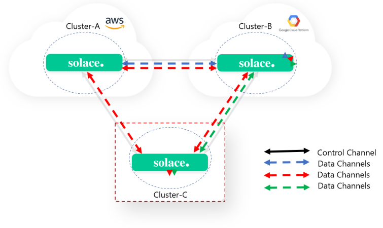
After you've configured the necessary cluster links, you can enable DMR for each Message VPN you want to participate in the clustering topology and link the Message VPNs together with DMR bridges. This configuration establishes data channels between nodes. Once a data channel is established, application messages are exchanged across nodes, as dictated by the subscription sets maintained over control channels.
This step assumes that you have the red, blue, and green Message VPNs created already via the create message-vpn <vpn-name> command. The names red, blue, green are placeholder strings for the Message VPNs in the sample commands—you should replace these with the names of your own Message VPNs. See Configuring Message VPNs for more information.
In this example, DMR is enabled for the red and blue Message VPNs on
Broker-A, the red, blue, and green Message VPNs on Broker-B,
and the red and green Message VPNs on Broker-C. The necessary DMR bridges to link
each Message VPN are also configured. This creates a set of data channels across the three sites.
To enable DMR for each participating Message VPN:
-
Log in to the
Broker-Ain clusterCluster-A, enter the Solace CLI, enable DMR on each participating Message VPN, and then create the necessary DMR bridges.Broker-A> enable Broker-A# config Broker-A(configure)# message-vpn
redBroker-A(configure/message-vpn)# dynamic-message-routing Broker-A(...e/message-vpn/dynamic-message-routing)# no shutdown Broker-A(...e/message-vpn/dynamic-message-routing)# create dmr-bridgeBroker-BBroker-A(...pn/dynamic-message-routing/dmr-bridge)# remote message-vpnredBroker-A(...pn/dynamic-message-routing/dmr-bridge)# exit Broker-A(...e/message-vpn/dynamic-message-routing)# create dmr-bridgeBroker-CBroker-A(...pn/dynamic-message-routing/dmr-bridge)# remote message-vpnredBroker-A(...pn/dynamic-message-routing/dmr-bridge)# exit Broker-A(...e/message-vpn/dynamic-message-routing)# exit Broker-A(configure)# message-vpnblueBroker-A(...e/message-vpn/dynamic-message-routing)# dynamic-message-routing Broker-A(...e/message-vpn/dynamic-message-routing)# no shutdown Broker-A(...e/message-vpn/dynamic-message-routing)# create dmr-bridgeBroker-BBroker-A(...pn/dynamic-message-routing/dmr-bridge)# remote message-vpnblue -
Log into the
Broker-Bin clusterCluster-B, enable DMR on each participating Message VPN, and create the necessary DMR bridges.Broker-B> enable Broker-B# config Broker-B(configure)# message-vpn
redBroker-B(configure/message-vpn)# dynamic-message-routing Broker-B(...e/message-vpn/dynamic-message-routing)# no shutdown Broker-B(...e/message-vpn/dynamic-message-routing)# create dmr-bridgeBroker-ABroker-B(...pn/dynamic-message-routing/dmr-bridge)# remote message-vpnredBroker-B(...pn/dynamic-message-routing/dmr-bridge)# exit Broker-B(...e/message-vpn/dynamic-message-routing)# create dmr-bridgeBroker-CBroker-B(...pn/dynamic-message-routing/dmr-bridge)# remote message-vpnredBroker-B(...pn/dynamic-message-routing/dmr-bridge)# exit Broker-B(...e/message-vpn/dynamic-message-routing)# exit Broker-B(configure)# message-vpnblueBroker-B(configure/message-vpn)# dynamic-message-routing Broker-B(...e/message-vpn/dynamic-message-routing)# no shutdown Broker-B(...e/message-vpn/dynamic-message-routing)# create dmr-bridgeBroker-ABroker-B(...pn/dynamic-message-routing/dmr-bridge)# remote message-vpnblueBroker-B(...pn/dynamic-message-routing/dmr-bridge)# exit Broker-B(...e/message-vpn/dynamic-message-routing)# exit Broker-B(configure)# message-vpngreenBroker-B(configure/message-vpn)# dynamic-message-routing Broker-B(...e/message-vpn/dynamic-message-routing)# no shutdown Broker-B(...e/message-vpn/dynamic-message-routing)# create dmr-bridgeBroker-CBroker-B(...pn/dynamic-message-routing/dmr-bridge)# remote message-vpngreen -
Log into the
Broker-Cin clusterCluster-C, enable DMR on each participating Message VPN, and create the necessary DMR bridges.Broker-C> enable Broker-C# config Broker-C(configure)# message-vpn
redBroker-C(configure/message-vpn)# dynamic-message-routing Broker-C(...e/message-vpn/dynamic-message-routing)# no shutdown Broker-C(...e/message-vpn/dynamic-message-routing)# create dmr-bridgeBroker-ABroker-C(...pn/dynamic-message-routing/dmr-bridge)# remote message-vpnredBroker-C(...pn/dynamic-message-routing/dmr-bridge)# exit Broker-C(...e/message-vpn/dynamic-message-routing)# create dmr-bridgeBroker-BBroker-C(...pn/dynamic-message-routing/dmr-bridge)# remote message-vpnredBroker-C(...pn/dynamic-message-routing/dmr-bridge)# exit Broker-C(...e/message-vpn/dynamic-message-routing)# exit Broker-C(configure)# message-vpngreenBroker-C(configure/message-vpn)# dynamic-message-routing Broker-C(...e/message-vpn/dynamic-message-routing)# no shutdown Broker-C(...e/message-vpn/dynamic-message-routing)# create dmr-bridgeBroker-BBroker-C(...pn/dynamic-message-routing/dmr-bridge)# remote message-vpngreen
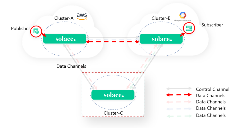
Step 5: Verify Data Channels Are Operational
At this point, you've configured all the necessary components to enable DMR on your network of PubSub+ event brokers. To verify that the DMR configuration is successful and working as intended, publish messages to a topic on one of the nodes, and acknowledge that you can consume the messages from a queue with a matching topic subscription on a node at another site. Before you start this step, you must create a queue on Broker-B with a matching subscription of a/b. For information about adding a topic, see Adding Topic Subscriptions to Queues
To verify that data channels are operational using SDKPerf:
-
Publish messages to a node at one of the sites.
sdkperf_c -cip=192.0.2.1:55443 -ptl=a/b -mn=50 -mr=50 -md -cu=user1@red
...
Waiting for publishing to complete.  Ctrl-c to exit.

Allow clients to finish receiving. Waiting: 2 secs
-----------------------------------------------------
Aggregate Msgs Sent Stats (Total # clients: 1)
Total Messages transmitted                 = 50
Computed publish rate (msg/sec)            = 49.99

-----------------------------------------------------
Aggregate Msgs Recv Stats (Total # clients: 1)
Total Messages received across all clients = 0
Computed receive rate (msg/sec aggregate)  = 0.00
Messages received with discard indication  = 0
-
Subscribe to a queue with a matching topic subscription on a node at another site, and verify that the published traffic is received by the subscriber.
sdkperf_c -cip=192.0.2.2:55443 -sql=Q1
...
Receiving messages.  Ctrl-c to exit.

-----------------------------------------------------
Aggregate Msgs Sent Stats (Total # clients: 1)
Total Messages transmitted                 = 0
Computed publish rate (msg/sec)            = 0.00

-----------------------------------------------------
Aggregate Msgs Recv Stats (Total # clients: 1)
Total Messages received across all clients = 50
Computed receive rate (msg/sec aggregate)  = 14626.11
Messages received with discard indication  = 0