Connections, LEDs, and Specifications
This section describes panel views, connections and LEDs, and technical specifications for Solace PubSub+ 3260s.
3260 Front Panel View
The two recessed buttons located below the LEDs provide the mechanisms for manually resetting the appliance. Labeled  and RST, these buttons can be activated with a paper clip.
- The () on/standby button can be used to toggle appliance power on or to a low power state.
- The RST button can be used to immediately reset and reboot the appliance without the cooperation of any software or operating system on the appliance.
Do not use the or RST buttons unless necessary. For example, if an appliance fails to respond for an extended time period, use of one of these recessed buttons may be necessary to correct the issue. However, both these recessed buttons will cause a disruption to service since they restart the appliance.
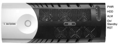
| Field Name | Color | Unlit Indicates | Lit Indicates |
|---|---|---|---|
|
PWR |
Blue |
Power is off |
Power is on. |
|
HDD |
Blue |
OK |
Hard Disk Drive (HDD) is being accessed. |
|
ALM |
Red |
OK |
The ALM LED flashes until the Solace PubSub+ software successfully turns up on the appliance. If the flashing continues for longer than ten minutes, this means the appliance has failed to turn up. A common cause is that there is only one power supply installed or working. Two installed and working power supplies are required for the Solace PubSub+ 3260 to turn up successfully. If you require assistance, contact Solace. |
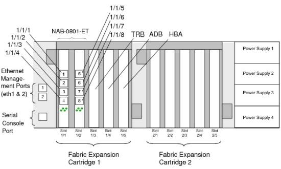
3260 Rear Panel View
Each Solace PubSub+ 3260 can support up to two Fabric Expansion Cartridges (FECs). Each FEC contains five blade slots. The supported FEC blade configurations (as viewed from the rear of the appliance chassis) for Version 7.1.2 and later are listed in the tables below.
All other FEC configurations available before Version 7.1.2 are still supported. Contact Solace for details.
All connections for the Solace PubSub+ 3260 are found at the rear of the device.
Like the Red ALM LED on the front panel, the Yellow Serial Console Port LED flashes until the Solace PubSub+ software successfully turns up on the appliance. If the flashing continues for longer than 10 minutes, this means the appliance has failed to turn up. A common cause is that there is only one power supply installed or working (two installed and working power supplies are required for the Solace PubSub+ 3260 to turn up successfully). If you require assistance, contact Solace.
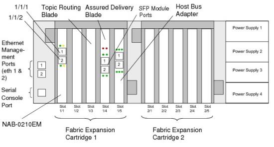
Rear Panel View of 3260 with NAB-0210EM-04

| Blade Type | Valid Blade Slots |
|---|---|
|
NAB-0210EM-01 |
1/1 |
|
NAB-0801ET-01 |
1/1 and 1/2 |
|
TRB-00000-01 |
1/3 |
|
ADB-000000-02 |
1/4 |
|
ADB 04210M-01-A |
1/4 |
|
Host Bus Adapter (HBA) |
1/5 |
HBA LED Status Indication
| Yellow LED | Green LED | Amber LED | Indicates |
|---|---|---|---|
| Off | Off | Off | Power off |
| On | On | On | Power on (before firmware initialization) |
| Flashing | Flashing | Flashing | Power on (after firmware initialization) |
| Yellow, green and amber LEDs flashing alternatively | Yellow, green and amber LEDs flashing alternatively | Yellow, green and amber LEDs flashing alternatively |
Firmware error
|
| Off | Off | On and flashing | Online, 1 Gbps link/I/O activity |
| Off | On and flashing | Off | Online, 2 Gbps link/I/O activity |
| On and flashing | Off | Off | Online, 4 Gbps link/I/O activity |
| Flashing | Off | Flashing | Beacon |
3260 Technical Specifications
|
Weight |
57 lb. (26 kg) |
|
Dimensions |
4U rack-mountable chassis Height 7 x Width 17 x Depth 31 inches (177.8 x 431.8 x 787.44 mm) |
|
Environmental Requirements |
|
|
Space Requirements |
|
|
Airflow Direction |
In through the front and out through the back. |
|
Power |
Input Rating:100-240VAC, 8-4A, 47-63 Hz
|
|
Regulatory Compliance |
Safety: UL 60950-1; CSA 22.2 No. 60950-1-07 and EN 60950-1; CE Mark EMC: FCC Part 15 Class A; EN55022 Class A; EN55024; EN61000-3-2/3; CE Mark
|

