Modeled Event Meshes
Runtime Event Manager helps you create and maintain models of event flows within modeled event meshes. A modeled event mesh represents an actual event mesh or event flow operating in a specific runtime environment. Modeled event meshes help you define and visualize event flows between publishing and subscribing applications within your event-driven architecture (EDA).
You create modeled event meshes within environments. Environments in Solace Cloud represent the runtime environments within your organization. For example, you may have several development environments for different lines of business, testing environments, a staging environment, and a production environment. You can create modeled event meshes with the same name in different environments to represent the deployment of applications as they are operationally promoted to runtime event brokers in higher level environments.
You can build modeled event meshes using objects created in Designer. Alternatively, if you already have a functioning EDA, you can use discovered runtime data to populate Event Portal with objects that match your runtime event flows and create modeled event meshes for your existing runtime environment without manually creating all of the applications and events in Designer.
This section includes the following tasks:
- Creating a Modeled Event Mesh
- Viewing a Modeled Event Mesh
- Viewing Object Relationships
- Viewing Object Details
- Deleting a Modeled Event Mesh
For information about managing event brokers, applications, and events within a modeled event mesh see Building a Modeled Event Mesh.
Creating a Modeled Event Mesh
Event Portal Managers and Administrators can create modeled event meshes. When you create a modeled event mesh you specify whether it represents a Solace event mesh or a Kafka event flow. You can then add a model event broker that represents an operational event broker in the runtime. For more information, see Adding an Event Broker to a Modeled Event Mesh.
To create a modeled event mesh, perform these steps:
- Log in to the Solace Cloud Console if you have not done so yet. The URL to access the Cloud Console differs based on your
- On the navigation bar, select Runtime Event Manager
 .
. -
At the top-left, select the environment that you want to create the modeled event mesh in.

If you intend to model event flows through event broker services that have already been created in Cluster Manager, Solace recommends creating the modeled event mesh in the same environment as the event broker services.
- Click Create Modeled Event Mesh near the top-right corner of the screen.
- Enter a Modeled Event Mesh Name.
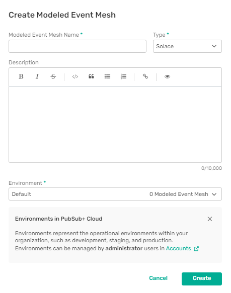
- Select either Solace or Kafka as the modeled event mesh Type.
- Enter a Description for the modeled event mesh. The Description field supports Markdown. Click toggle preview
 to preview the rendered text.
 - Click Create.
Viewing a Modeled Event Mesh
When you open a modeled event mesh, the Architecture tab displays the objects that the modeled event mesh contains, both in a list and in a graph that shows the relationships between the objects in the modeled event mesh.
Event Portal Users can open modeled event meshes only if the modeled event mesh is in an environment that the user has Viewer or Editor level access to. For more information, see Configuring Environment Access for Event Portal Users.
To view a modeled event mesh, perform these steps:
- On the navigation bar, select Runtime Event Manager .
- At the top-left, select the environment containing the modeled event mesh.
- Click the name of the modeled event mesh.
If you have added objects to the modeled event mesh, the Architecture tab includes a List panel and a Graph panel. Both panels display the objects in the modeled event mesh. When you select an object in either the list or the graph, it is highlighted in both panels. To start adding objects to a new modeled event mesh, see Building a Modeled Event Mesh.
The list view includes tabs for applications, events, and imported Kafka schemas. You can filter the list by name to find a specific object.
Using the Graph Panel
You can use the tools at the top of the Graph panel to adjust the view.
| Tool | Description |
|---|---|
|
Showing |
Specifies which subscription event flows display in the graph. You can select from these options:
If an application has both a declared intent to subscribe to an event and a consumer with a topic subscription that attracts the event, the event flow always shows in the graph, regardless of this setting. For more information about subscribing to events, see Creating Applications. |
|
|
Refreshes the graph with any updates to objects and layout changes made by other users, without recalculating the layout. |
|
|
Centers the graph on the page and, if necessary, zooms down to display all objects or zooms up to full size. |
|
|
Settings menu with these options:
|
|
|
Opens the legend to display information to help you use the graph |
|
|
Centers the graph on the page and, if necessary, zooms down to display all objects or zooms up to full size. |
|
|
Zooms in and out. |
The Graph panel uses the following icons to represent objects in your modeled event mesh:
| Icon | Description |
|---|---|
|
|
Application |
|
|
Application with a pending removal request. The application can be removed from an event broker in the modeled event mesh after the request is approved. For more information, see Reviewing Promotions to Event Brokers. |
|
|
Application in draft state Applications in draft state are still in development and subject to change. If Show Warnings is enabled, a warning indicator displays over the icon if there are discrepancies in the application event flows. Right-click the application and select View Details for more information about the issue. For more information, see Applications. |
|
|
Event |
|
|
Event in draft state Events in draft state are still in development and subject to change. If Show Warnings is enabled, a warning indicator displays over the icon if the event does not have a topic address or if there is no application in the modeled event mesh that publishes it.Right-click the event and select View Details for more information about the issue. |
|
|
Unpublished event If Show Warnings is enabled, a warning indicator displays over the icon. |
|
|
Schema Schemas display only in the Relationship view. |
|
|
Locked object Event Portal Users see a lock on non-shared objects in application domains that they don't have at least Viewer level access to. |
|
|
Event path The arrow indicates the direction of the event. If the arrow points away from an application, the application publishes the event. If the arrow points toward an application, the application subscribes to or consumes the event. If an issue needs to be fixed with an event or with an application that publishes it or subscribes to it, the event path appears as a dashed line. |
If you have at least Editor level access to the modeled event mesh, you can also drag objects around the graph. If you drag an object to a new location on the screen, the view changes for all users. To select multiple objects to move at the same time, press Control while clicking objects or press Shift while dragging over objects.
Event Portal Users can see all applications and events that have been added to the modeled event mesh but can't open applications and non-shared events in application domains that they don't have access to.
Viewing Object Relationships
If you have a modeled event mesh that contains a large number of objects, you may find it useful to view only a specified object and the other objects that it is closely related to, so you can better visualize the relationships between a smaller number of objects.
Event Portal Users can see relationships with all applications and events that have been added to the modeled event mesh but can't open or view details for applications and non-shared events in application domains that they don't have access to.
To view the relationships for an object, perform these steps:
-
On the Architecture tab for the modeled event mesh, right-click an object in the Graph panel and select Show Relationships.
Alternatively, in the List panel, click More Actions
 for the object and select Show Relationships.
 -
Click Settings
 to specify how the relationships for the specified object display using the following options:
Option Description Show Warnings
When this option is enabled, warning icons and tooltips for applications with unconsumed events, events with no topic address, and unpublished events, display in the Graph panel.
Show Schemas
When this option is enabled, schemas associated with events in the Relationship view also display if they are within the selected number of relationship levels. Schemas display for both Solace and Kafka modeled event meshes. Schemas shown in the Relationship view appear in the List panel only if they were imported into Event Portal.
Event Portal Users can see schemas only if they are shared or in application domain that the user has access to.
Layout Style
The Relationship view can display objects in a Tree layout with the specified object at the top or a Radial layout with the specified object in the center.
Relationship Level
You can display one level of relationships to show only the objects directly associated with the specified object or two levels to also show objects directly associated with the first level of related objects.
If you display two levels of related objects using the Radial layout, some objects may display more than once. For example, if you show the relationships for an event that is associated with two applications, any other events associated with both applications display twice to show the relationships for both applications.
If you select an object that displays more than once, all other instances are highlighted.
Reset Layout
If you drag objects to new positions while in the Relationship view, this option resets the objects back to their initial positions.
Unlike the full Graph view, if you drag objects around the Graph panel in the Relationship view, the object positions are reset whenever you go back to the Graph view, view relationships for a different object, or change the layout style or number of levels displayed.
- To return to the full graph, click Back to Graph View.
Viewing Object Details
You can view the design details of the application, event, and schema versions that display on the Architecture tab if you have at least Viewer level access to the application domain.
You can also open the object in Designer from the Details dialog.
To view application, event, or schema version details, perform these steps:
-
On the Architecture tab for the modeled event mesh, right-click on an object in the Graph panel and select View Details.
Alternatively, in the List panel, click the name of the object.
- To open the object in Designer, in the Details dialog, click Open in Designer.
Deleting a Modeled Event Mesh
Administrators and Event Portal Managers can delete modeled event meshes that you no longer need. When you delete a modeled event mesh, the application versions and event versions it includes are not deleted from Event Portal or from other modeled event meshes. Model event brokers that are part of a modeled event mesh and remain in Event Portal become available to add to another modeled event mesh.
To delete a modeled event mesh, perform these steps:
- On the navigation bar, select Runtime Event Manager .
- At the top-left, select the environment that you want to delete the modeled event mesh from.
- In the list of modeled event meshes, click More Actionsfor the modeled event mesh that you want to delete and then select Delete.
- Click Delete.