High Availability for Appliance Event Brokers
Solace Appliance Event Brokers can operate in high-availability (HA) redundant pairs for fault tolerance. Redundancy provides 1:1 appliance event broker sparing to increase overall service availability. HA redundancy eliminates the potential for a single point of failure by allowing a network administrator to define two appliance event brokers as a redundant pair. If one of the appliance event brokers is taken out of service or fails, the other appliance event broker automatically takes over responsibility for the clients typically served by the out-of-service appliance event broker.
The redundancy feature is largely transparent to clients and other appliance event brokers in the network. Only the two appliance event brokers that are paired as mates require explicit configuration to take advantage of the feature.
Similarly, there is no configuration needed on a client host system to take advantage of the HA redundancy facility. The only visible impact to clients during a redundancy failover is non-delivery of messages for a short period of time, and the clients are forced to reconnect.
The Virtual Router Redundancy Protocol (VRRP), as defined by Request For Comments (RFC) 3768, is used to manage the IP address used by clients to communicate with appliance event brokers. The appliance event broker that is active for a given IP address terminates all client messages sent to that IP address. If the active appliance event broker fails, the backup appliance event broker takes over the IP address. Therefore, migration of the IP address and messaging services from one appliance event broker in the HA pair to its mate appliance event broker allows clients to reconnect to the same IP address which is now managed by the mate appliance event broker.
Solace Platform redundancy models are built around the concept of virtual routers:
- If an active/standby model is deployed: One virtual router with a unique IP address must be configured for the redundant pair. This virtual router is configured as the primary on one appliance event broker and as the backup on its mate.
- If an active/active model is deployed: Two virtual routers must be configured within the redundant pair, each with its own unique IP address. One appliance event broker is configured as the primary for one of the virtual routers (and backup for the second virtual router), while the second physical appliance event broker is configured as the primary for the other virtual router (and backup for the first virtual router).
Under normal operating conditions, the physical appliance event broker that is active for the primary virtual router handles messaging activity. If that appliance event broker fails, the mate appliance event broker takes over activity for the virtual router.
Under normal operating conditions, each appliance event broker is active for its primary virtual router, and standby for the mate's virtual router. If one of the appliance event brokers fails, the mate appliance event broker takes over activity for the virtual router associated with the failed appliance event broker.
Active/Standby Redundancy Model
Active/standby redundancy is supported by Solace Platform for both Guaranteed and Direct Messaging.
In the active/standby model, the primary appliance event broker provides service to clients and sends and receives data and messages. The backup appliance event broker waits in standby mode and only provides service should the primary appliance event broker fail .
In the active/standby model:
- All clients connect to the same virtual router, which is configured as primary for one appliance event broker and as backup on its mate appliance event broker.
- The backup appliance event broker acts only as a standby. While the primary appliance event broker is active, no clients can connect to the backup, and no messaging traffic can flow through the backup.
- If the primary appliance event broker fails for any reason, the backup appliance event broker takes over the IP address of the virtual router associated with the failed appliance event broker by sending gratuitous Address Resolution Protocol (ARP) requests, and all the clients reconnect to the backup appliance event broker.
Active/Active Redundancy Model
Active/active redundancy is supported by the Solace Platform for Direct Messaging.
In the active/active model, clients may be distributed between the two appliance event brokers, and both appliance event brokers can provide service simultaneously during normal operating conditions. This allows for load-sharing while both appliance event brokers are functional. However, should one of the appliance event brokers fail for any reason, the active appliance event broker can provide the service ordinarily provided by both of the appliance event brokers individually.
In the active/active model:
- One appliance event broker is active for one virtual router, while the other appliance event broker is active for the second virtual router.
- Clients actively connect to both virtual routers (thus to both appliance event brokers) and both appliance event brokers carry messaging traffic.
- If one of the appliance event brokers fails, the mate appliance event broker takes over the IP address of the virtual router associated with the failed appliance event broker by sending gratuitous ARPs, and all the clients associated with the failed appliance event broker reconnect to the backup appliance event broker.
Two variants of the active/active redundancy model can be deployed:
- Individual Message VPNs are Active/Standby
- Individual Message VPNs are Active/Active
In this deployment model, all clients for one group of Message VPNs are configured to connect to virtual router #1, and all clients for a separate group of Message VPNs are configured to connect to virtual router #2. That is, all clients for a given Message VPN are configured to be serviced by one appliance event broker in the redundant pair.
In this deployment model, clients of a given Message VPN span the two appliance event brokers in the redundant pair, with the clients divided between the virtual routers. For this model to provide full reachability between all clients of the distributed Message VPN at all times, either multiple-node routing links or Message VPN bridge links must be provisioned to provide connectivity between the two appliance event brokers.
Guaranteed Messaging may also be configured in conjunction with Direct Messaging, however, only one appliance event broker may provide Guaranteed Messaging service at any given time. That is, while the Redundancy Mode can be configured as Active/Active where both appliance event brokers support Direct Messaging concurrently, Guaranteed Messaging will operate in Active/Standby mode on one virtual router.
Recommended Redundancy Model
Solace recommends deploying appliance event brokers in the active/standby model, for the following reasons:
- Active/standby supports both Guaranteed and Direct Messaging.
- Active/standby avoids the risk of inadvertent overbooking an appliance event broker, whereby each appliance event broker has sufficient capacity to handle the messaging load for its own virtual router, but under a failure scenario, a single appliance event broker has insufficient capacity to handle the workload of the two virtual routers, resulting in an unacceptable service degradation that is not exposed until a failover occurs.
- Lower engineering/planning overhead. No need to decide which Message VPNs are going to reside within each virtual router, or which clients will connect to which virtual router.
- Active/standby is an easier model to test and validate prior to going into production.
If you are using Solace Cache, we do not recommend using the active/standby redundancy model, unless it is the only redundancy model that is possible for your use case. For more information, see Solace Cache and Event Broker Redundancy.
Fault Tolerance
The following sections discuss the interaction between primary and virtual routers and primary and backup IP interfaces in appliance event broker failover situations. It also provides network topology examples.
Primary and Backup Virtual Routers
To support redundancy, each appliance event broker uses a primary and backup virtual router. To enable the backup virtual router to assume the role of its mate's primary virtual router when a failure occurs, the configuration of the virtual routers on each appliance event broker must mirror one another. That is, the backup virtual routers must have the same configuration as the primary virtual routers they backup.
For an Active/Standby redundant pair
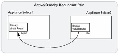
For an active/standby redundant pair, the primary virtual router is on the primary appliance event broker, and the backup virtual router is on the standby appliance event broker. If the primary appliance event broker goes out of service, the backup virtual router of the standby appliance event broker changes to an active state, and it provides service for clients and handles the data and messages that typically use the primary virtual router of the primary appliance event broker that has gone out of service. The figure below shows the relationship between the virtual routers of an active/standby redundant pair.
Virtual Router Relationships in an Active/Standby Redundancy
|
Appliance Event Broker |
supports. |
Appliance event broker |
For an Active/Active redundant pair
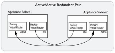
For an active/active redundant pair, the primary virtual routers on both appliance event brokers are active, but the backup virtual routers are idle. If one of the appliance event brokers in the redundant pair goes out of service, the backup virtual router of the inactive appliance event broker changes to an active state, and it provides service for clients and handles the data and messages that typically use the primary virtual router of the appliance event broker that is out of service. The figure below shows the relationship between the virtual routers of an active/active redundant pair.
Virtual Router Relationships in Active/Active Redundancy
|
Appliance event broker |
supports. |
Appliance event broker |
|
Appliance event broker |
supports. |
Appliance event broker |
The primary and backup virtual routers are served by the Message Backbone Virtual Routing and Forwarding (VRF) object. Through the physical interfaces located on the Network Acceleration Blade (NAB), the Message Backbone VRF handles the client traffic (including subject subscriptions) for the virtual routers.
Primary and Backup IP Interfaces
For each appliance event broker, physical interfaces on the NAB must be bound to distinct IP interfaces that are identified by an IP address and subnet mask. Clients connect to these IP interfaces. These primary and backup IP interfaces are associated with the primary and backup virtual routers on each appliance event broker in the redundant pair.
For an Active/Standby redundant pair
The example immediately below shows a simplified example of the primary and backup IP interfaces and virtual routers used by an active/standby redundant pair. In a failover situation, clients can reconnect to the backup IP interface.
Simplified Active/Standby Configuration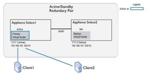
For an Active/Active redundant pair
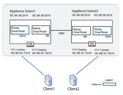
To enable active/active redundancy, primary and backup instances of the IP interfaces are created for each appliance event broker in a redundant pair. The same IP interfaces are used by each appliance event broker, but they are assigned as primary on one and as backup on the other. Therefore, if one appliance event broker goes out of service, a backup IP interface can still be accessed by the client on the inactive appliance event broker.
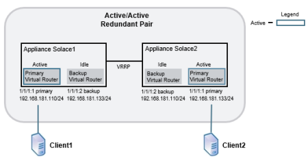
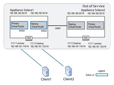
Below is shown a simplified example of the primary and backup IP interfaces and virtual routers used by an active/active redundant pair, and then the same redundant pair is shown in a failover situation.
- On appliance event broker
Solace2, the physical interface 1/1/1 contains two IP interfaces. 1/1/1:1 is configured as the primary IP interface with IP address 192.168.181.133/24, and 1/1/1:2 is configured as the backup IP interface with IP address 192.168.181.110/24. - To maintain service if appliance event broker
Solace2goes down, the mate appliance event broker,Solace1, also contains the IP interfaces 1/1/1:1 and 1/1/1:2. However the IP addresses assigned to these IP interfaces are reversed. ForSolace1, the primary IP interface 1/1/1:1 is configured with IP address 192.168.181.110/24, and the backup IP interface 1/1/1:2 is configured with IP address 192.168.181.133/24.
An IP number from 1 to 3 indicates the type of IP interface (primary, backup, or static). A typical association is 1 for primary, 2 for backup, and 3 for static, but this is not enforced.
Simplified Active/Active Configuration
Simplified Active/Active Configuration in Failover
VRRP interface
In addition to the IP interface that clients connect to, an appliance event broker uses a VRRP interface. Through this VRRP interface, both appliance event brokers of the redundant pair can communicate the status of their virtual routers. Primary and backup instances are required for each VRRP interface, and to enable redundancy, the IP addresses assigned for both primary VRRP interfaces must match the IP addresses for their backup VRRP interfaces.
Active/Standby Network Topology Example
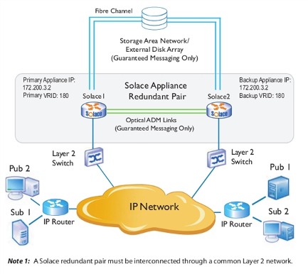
The example shown immediately below shows a physical network topology example for active/standby redundancy when used for Guaranteed Messaging. Only one appliance event broker in the redundant pair (Solace1) receives messages through the primary virtual router. For the other appliance event broker (Solace2), the same virtual router is configured as backup. However, should Solace1 fail, Solace2 will detect the failure and start providing service to the clients that were connected to Solace1.
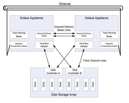
When active/standby redundancy is used with Guaranteed Messaging, a customer‑supplied external disk storage array is required, and each appliance event broker must have an ADB and an HBA.
In addition, when Guaranteed Messaging is used, a pair of redundant optical links connect the ADBs between the two appliance event brokers. The ADB optical link is used to propagate Guaranteed messages and states from the active appliance event broker to the standby appliance event broker. Whenever the standby appliance event broker becomes reachable over the ADB link, the active appliance event broker copies the entire ADB contents from the active to the standby appliance event broker over the ADB link. Any subsequent messages and state information which the active appliance event broker writes to the ADB is automatically propagated over the optical link to the ADB of the backup appliance event broker. This ensures that the message contents and state of the ADB in the backup appliance event broker are always in sync with the ADB of the active appliance event broker.
SAN Behavior for Guaranteed Messaging Through Active/Standby Redundancy
Each pair of appliance event brokers in an active/standby redundancy configuration require a separate Logical Unit Number (LUN) on the Storage Area Network (SAN), whereby two partitions are created on the LUN. One of the appliance event brokers mounts the first partition as "read/write" and the second partition as 'read only, while the mate appliance event broker mounts the first partition as 'read only' and the second partition as "read/write" (that is, the inverse of its paired appliance event broker).
The active appliance event broker in an active/standby redundant pair only ever writes to its "read/write" or active partition. In the case of a failover, it provides service for its mate by reading the messages spooled by its mate through the standby partition mounted as "read only".
Physical Network Topology Example for Active/Standby Redundancy
Basic Operation
If an appliance event broker detects that its mate is down, it asserts an activity switch on behalf of its mate.
The basic operational activity is:
- The primary appliance event broker periodically advertises that it is active for its VRID.
- If the primary appliance event broker stops advertising for a predetermined period of time, the backup appliance event broker using the same VRID takes over message forwarding responsibilities from the primary. The backup appliance event broker is now active.
Failure Detection
As shown in the figure of the redundant HA pair immediately above, there are several paths of connectivity between the redundant appliance event broker pair. The redundancy state machines within each appliance event broker monitors the status of the mate appliance event broker through the following communication paths:
- VRRP over the Layer 2 Network: VRRP is always employed between a redundant pair of appliance event brokers to communicate activity status, and to detect a failure of the mate appliance event broker.
- Multiple-Node Routing: If the appliance event brokers have been configured as CSPF neighbors in multiple-node routing, then the activity status of the appliance event brokers is advertised as part of the periodic "hello" messages sent by CSPF.
- ADB Optical Links: If the appliance event brokers are equipped with ADBs for Guaranteed Messaging, then the activity status of the appliance event brokers is advertised over the fibre links that interconnect the ADBs on the two appliance event brokers.
An active appliance event broker may decide to voluntarily release activity to the standby appliance event broker by sending a "releasing-activity" indication over all the inter-event broker communication paths. However, to prevent the possibility of paired appliance event brokers becoming primary simultaneously and creating a split-brain scenario, the standby appliance event broker does not take activity until it receives a "releasing-activity" indication, or detects a loss of connectivity on all three of the communication paths described above.
Once an appliance event broker has taken activity, it typically does not pro-actively send a "releasing-activity" indication to its mate unless one of the following events occur:
- A release-activity Redundancy CONFIG or revert-activity Admin EXEC command is executed through the Solace Event Broker CLI or SEMP.
- The appliance event broker detects that it has lost all Layer 2 connectivity on the NAB.
- The appliance event broker detects that it has lost all connectivity to the SAN.
- The appliance event broker detects a fault that requires it to restart.
Under some fault conditions, the failing appliance event broker may not always be able to send a "releasing-activity" indication to its mate before restarting. However, such a restart causes an interruption of all three communication paths, which after a debounce time of several seconds on the mate appliance event broker, causes the mate appliance event broker to take activity.
Failover Sequences
This section discusses the failover sequences that occur for:
-
For a list of the most common reasons for an HA failover, see Event Broker Failure Activity Switch.
-
A number of event broker priority levels have been defined for redundancy. These priority levels are advertised by the virtual routers. When activity switches occur between redundant pairs, the priority levels advertised by the virtual routers of each appliance event broker change to indicate their current state and role. These advertisements are broadcast between redundant pairs through VRRP. For example, the virtual router that advertises the highest priority level for a given VRID is the active virtual router for that VRID. All messages and system requests for that VRID are then forwarded to that virtual router.
Event Broker Failure Activity Switch
This is a list of the most common reasons for a failover scenario:
- reset or power-cycle of the event broker (transient outage, planned or unplanned)
- hardware failure of the event broker (longer-term outage, unplanned)
- physical link to the event broker is down (could be transient or longer-term, planned or unplanned)
- software upgrade of the event broker (transient outage, planned)
- event broker has been placed in the standby state as a result of the network operator entering the release-activity Redundancy CONFIG command through the Solace Event Broker CLI (longer-term outage, planned)
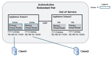
The following figure shows an example of an active/active network configuration.
Active/Active Redundant Pairing
Using this example the following series of operations occur if one of the appliance event brokers (Solace2 in this case) goes out of service for any reason:
- VRRP on appliance event broker
Solace1detects the failure of appliance event brokerSolace2. Solace1becomes active for the IP address 192.168.181.133/19. When this occurs, the backup virtual router forSolace1goes from an idle state to an active state.Solace1increases the priority of its VRRP advertisements for the IP address 192.168.181.133/19 to Assert-Activity. It also sends out a gratuitous ARP to let other network devices know that it is taking over the IP address. At this point, network traffic to the IP address 192.168.181.133/19 flows toSolace1.- Clients that had already established TCP connections to
Solace2receive error messages back fromSolace1because the TCP connections are not present onSolace1. This causes the clients to tear down the existing TCP sessions and immediately establish new TCP sessions. These new connections are accepted bySolace1. Solace1accepts subscription updates and published messages from its own clients and those that typically have service fromSolace2.
Active/Standby Using Guaranteed Messaging
If an active/standby redundancy model for Guaranteed Messaging is used for the redundant pair, the failure of the primary appliance event broker is detected through the VRRP link between the appliance event brokers. In addition, the failure is also detected by the ADB link—the standby appliance event broker uses the state from its local ADB to continue to provide service. The figure below shows the links used between active/standby appliance event brokers.
Links Used by Active/Standby Appliances Using Guaranteed Messaging
Appliance Event Broker Recovery Activity Switch
The figure below shows a common recovery activity switch scenario for an active/active redundant pair, where appliance event broker Solace2 has failed and its mate appliance event broker, Solace1, is acting on behalf of Solace2.
Activity Switch Behavior Failure
When appliance event broker Solace2 comes back online, the following series of operations occur:
- As
Solace2starts up, its primary virtual router uses a VRRP advertisement of Primary-Reconcile, and its backup virtual router uses a VRRP advertisement of Backup-Reconcile. These advertisements indicate that the virtual routers are initializing, but are not yet ready to take on client activity. - The appliance event brokers are deployed in an active/active redundancy model.
- The redundant pair has been deliberately "overbooked" beyond the capacity of a single appliance event broker, so that service will degrade when one of the appliance event brokers is off-line.
- The disruption caused by the momentary service outage during auto revert is considered less harmful than continuing to run in an overbooked state until service can be manually reverted during a service window.
- Once
Solace2has fully started, its primary virtual router increases the priority of its VRRP advertisements to Assert-Activity. This priority level causes the backup virtual router of its mate system to relinquish activity.Solace2then sends a gratuitous ARP to let the other network services know it is taking over the IP address 192.168.181.133/19 for client connections. Solace1disconnects any TCP sessions that it had established for clients receiving service from IP address 192.168.181.133/19.- The old active appliance event broker unmounts the disk partitions.
- The newly active appliance event broker mounts both disk partitions as "read only" then probes the AdKey. If no conflict is detected, the disk partitions are mounted as described in SAN Behavior for Guaranteed Messaging Through Active/Standby Redundancy (that is, the active LUN partition is mounted as "read/write", and the standby LUN partition is mounted as "read only").
- Garbage collection may be done in the background where messages spooled on the newly active partition have already been delivered or administratively deleted (since it was previously read-only so file cleanup was not possible).
- The primary virtual router for
Solace1advertises a local priority level of Active, and the backup virtual router advertises a local priority level of Backup. Solace2accepts new TCP connections to IP address 192.168.181.133/19 and delivers messages to, and accepts messages from, clients using this IP address.
If Guaranteed Messaging is enabled for the redundant pair, the ADB on Solace1 transfers its entire contents to the ADB on Solace2 over the ADB links.
If auto revert is enabled (b), then the following series of operations also occur:
By default auto revert is not enabled, which is preferable for most situations. However, you may want to enable auto revert so that clients revert to their primary appliance event broker as soon as it comes back online when all of the following conditions are met:
For an HA appliance event broker pair that is configured for only Direct Messaging, auto-revert behavior may be exhibited under specific network outages where VRRP communication is lost for over three seconds even if the auto-revert option is disabled. This is to prevent the possibility of both appliance event brokers entering a split-brain scenario when VRRP communication is lost. For more information, refer to Auto-Revert Behavior of HA Appliance Event Brokers Using Only Direct Messaging.
If Guaranteed Messaging is enabled for the redundant pair, on redundancy switchover the following steps also occur:
Through the auto-revert Redundancy CONFIG command, the network administrator can configure whether the standby appliance event broker in a redundant pair should automatically revert back at this point to the primary when the primary comes back online after a service outage.
Auto-Revert Behavior of HA Appliance Event Brokers Using Only Direct Messaging
Auto-revert behavior may be exhibited under specific network outages where VRRP communication is lost for over three seconds, even if the auto-revert option is disabled. In this situation, if activity has failed over to the backup, when the VRRP communication is recovered the primary appliance event broker will forcefully take activity for the virtual message router. This occurs to prevent the possibility of both appliance event brokers entering a split-brain scenario when VRRP communication is lost. This is applicable for both active/standby and active/standby HA appliance event broker pairs.
In the event that a failover occurs due to any other cause, the auto-revert behavior depends on whether it is enabled. If auto-revert is disabled, the backup appliance event broker remains active after the primary appliance event broker comes back online.
Subscription Exporting & Message VPNs
As discussed in Enabling Subscription Export, each Message VPN has a topic subscription export policy associated with it and the default mode is set to not exporting subscriptions.
If a Message VPN is not exporting topic subscriptions, then clients connected to one appliance event broker in an active/active appliance event broker pair do not receive messages from clients connected to another appliance event broker in the pair. However, if a failure occurs such that the clients from both virtual routers end up connected to the same appliance event broker, then messages can be passed between clients on different virtual routers.
This is because the topic subscriptions are then maintained within the scope of the appliance event broker, since the Message VPN export policy does not apply between virtual routers hosted on the same appliance event broker.
To avoid this scenario, either:
- Deploy the redundant pair in an active/standby configuration.
- For Message VPNs not exporting topic subscriptions all clients of the Message VPN should connect to the same virtual router so that the Message VPN is effectively deployed in an active/standby configuration.
VPN Bridging & Fault Tolerance
For details on how to establish Message VPN bridge connections to remote appliance event brokers when those remote appliance event brokers have been deployed in a redundant configuration to provide fault tolerance, refer to Bridging to Remote Event Brokers That Use Redundancy.
Next Steps
- HA Configuration for Appliance Event Brokers shows you how to set up and use redundancy.